The relays are switching DC at 12V, but the polarity is determined
before the on/off relay. Most SS relays I've seen are triac-based for AC only; one type would do DC, but not with the polarity changing (and at
10x the cost anyway!).
Hi - I'm working on a model railway project using pico boards, but have spotted something that ought to be improved.
The power to each section of track is scheduled to be switched by a
relay. I've a bank of 8 traditional relays, but have just realized the
total relay current will be up to a half amp or so worst case. I'm
looking to a solid state solution.
The relays are switching DC at 12V, but the polarity is determined
before the on/off relay. Most SS relays I've seen are triac-based for AC only; one type would do DC, but not with the polarity changing (and at
10x the cost anyway!).
Does anyone know anything solid state that might do this without
breaking the bank?
Thanks.
Mike Scott wrote:
The relays are switching DC at 12V, but the polarity is determined
before the on/off relay. Most SS relays I've seen are triac-based for
AC only; one type would do DC, but not with the polarity changing (and
at 10x the cost anyway!).
You could use a H-bridge, rather than build it from discrete transistors/FETs they come as a single or dual bridge in an IC, possibly with built-in snubber network.
Actually re reading the question he wants a *polarity neutral* switch.
That is not easy. And is not exactly what an H bridge will do.
But realistically I'd probably use a 3.3 or 5V Songle relay. They are
uber cheap in bulk from Aliexpress.
Hi - I'm working on a model railway project using pico boards, but have spotted something that ought to be improved.
The power to each section of track is scheduled to be switched by a relay. I've a bank of 8 traditional relays, but have just realized the total
relay current will be up to a half amp or so worst case. I'm looking to a solid state solution.
The relays are switching DC at 12V, but the polarity is determined before the on/off relay. Most SS relays I've seen are triac-based for AC only;
one type would do DC, but not with the polarity changing (and at 10x the cost anyway!).
Does anyone know anything solid state that might do this without breaking the bank?
On 01/08/2025 10:24, Andy Burns wrote:
Mike Scott wrote:
The relays are switching DC at 12V, but the polarity is determined >>>before the on/off relay. Most SS relays I've seen are triac-based forYou could use a H-bridge, rather than build it from discrete >>transistors/FETs they come as a single or dual bridge in an IC,
AC only; one type would do DC, but not with the polarity changing
(and at 10x the cost anyway!).
possibly with built-in snubber network.
I am not familiar with how todays model railways actually work. I
thought they had electronics in them to control speed and direction.
The power to each section of track is scheduled to be switched by a relay. ... I'm looking to a solid state solution.
Does anyone know anything solid state that might do this without breaking the bank?
.....
I am not familiar with how todays model railways actually work. I
thought they had electronics in them to control speed and direction.
Some people are still using the traditional DC systems, others use DCC, which requires electronics in each loco.
If you can drive relays momentarily but not continuously, consider
bistable relays.
But realistically I'd probably use a 3.3 or 5V Songle relay. They areAgreed, I think that's the simplest solution here.
uber cheap in bulk from Aliexpress.
On 01/08/2025 15:00, Adrian wrote:
.....
I am not familiar with how todays model railways actually work. I
thought they had electronics in them to control speed and direction.
Some people are still using the traditional DC systems, others use
DCC, which requires electronics in each loco.
plus ££££££
I was trying to get something simple done on the cheap. The expense of
DCC would barely be justifiable.
On 01/08/2025 12:51, Theo wrote:
But realistically I'd probably use a 3.3 or 5V Songle relay. They areAgreed, I think that's the simplest solution here.
uber cheap in bulk from Aliexpress.
I'm beginning to agree. I've been hunting round for prebuilt modules to
do the trick, and nothing provides isolation like a good old-fashioned relay. Maybe I just have to put up with the current drain.
Many thanks to all who've responded with ideas. I'll look around a bit
more, then press on with the relay bank.
Well its only 70mA a relay When its on
On 01/08/2025 14:49, David Higton wrote:
If you can drive relays momentarily but not continuously, consider
bistable relays.
I do have some, bought for another part of the project. But at IIRC ~£7
a pop, they're not cheap: I need 8.
On 01/08/2025 17:52, The Natural Philosopher wrote:
Well its only 70mA a relay When its on
x8 though, worst case. Over half an amp. Seemed a lot just to let some current through to the tracks.
On 01/08/2025 17:52, The Natural Philosopher wrote:
,,,
.
Well its only 70mA a relay When its on
x8 though, worst case. Over half an amp. Seemed a lot just to let some current through to the tracks.
beefy set of MOSFETs in a H-bridge circuit, which had
nevertheless been blown apart when the owner hooked the power
supply up backwards.
Hi - I'm working on a model railway project using pico boards, but have >spotted something that ought to be improved.
The power to each section of track is scheduled to be switched by a
relay. I've a bank of 8 traditional relays, but have just realized the
total relay current will be up to a half amp or so worst case. I'm
looking to a solid state solution.
The relays are switching DC at 12V, but the polarity is determined
before the on/off relay. Most SS relays I've seen are triac-based for AC >only; one type would do DC, but not with the polarity changing (and at
10x the cost anyway!).
Does anyone know anything solid state that might do this without
breaking the bank?
In article <106hurs$9ibr$1@dont-email.me>,
Mike Scott <usenet.16@scottsonline.org.uk.invalid> wrote:
Hi - I'm working on a model railway project using pico boards, but have
spotted something that ought to be improved.
The power to each section of track is scheduled to be switched by a
relay. I've a bank of 8 traditional relays, but have just realized the
total relay current will be up to a half amp or so worst case. I'm
looking to a solid state solution.
The relays are switching DC at 12V, but the polarity is determined
before the on/off relay. Most SS relays I've seen are triac-based for AC
only; one type would do DC, but not with the polarity changing (and at
10x the cost anyway!).
Does anyone know anything solid state that might do this without
breaking the bank?
So you're looking for an AC SSR. Forget that the polarity is switched
before the relay as to all intents and purposes it's effectively AC.
The main issue I had when doing this on a Pi some years back was that all
the SSRs I used had a 5v input voltage with built-in limiting resistors on the opto isolator part. Saying that, I didn't find one that wouldn't work with the Pi's 3.3v output. I've no experience of the Picos outputs though.
I was switching 240v AC not 12v AC - and there is another issue - a lot of them
are aimed at higher voltages - say 36-240v AC
Searching ebay find this for example:
https://www.ebay.co.uk/itm/166442394010
it's actually rated 3 to 32v input but the output is >= 24v AC so it may
not turn on at 12v. Also be aware that triac based ones may be relying
on the zero crossing to turn off, so once on, it might remain on even
when you remove the control voltage. I suspect the ones with GTO switches
are the more expensive ones.
Personally, I think that if I already had a working bank of mechanical
relays (with opto isolated inputs such as the multitude sold for Adruino
and Pi) I'd just suck it up and give it a separate 5v PSU capable
of driving the coils. (Or take the main system 5v and give it a good decoupling from the electronics side to minimise any interferance).
Sure, it may well be a waste of energy but half an amp at 5 volts is a
mere 2.5 watts. Run that continually for a year and that's 22 KWh which should be under a fivers worth of energy, but the chances of running it
like that are probably remote... (how much was the last coffee and cake
you bought?)
And mechanical relays will allow the passing of any DCC signals if you're using that.
-Gordon
So you're looking for an AC SSR. Forget that the polarity is switched
before the relay as to all intents and purposes it's effectively AC.
The main issue I had when doing this on a Pi some years back was that all
the SSRs I used had a 5v input voltage with built-in limiting resistors on the opto isolator part. Saying that, I didn't find one that wouldn't work with the Pi's 3.3v output. I've no experience of the Picos outputs though.
I was switching 240v AC not 12v AC - and there is another issue - a lot of them
are aimed at higher voltages - say 36-240v AC
Searching ebay find this for example:
https://www.ebay.co.uk/itm/166442394010
it's actually rated 3 to 32v input but the output is >= 24v AC so it may
not turn on at 12v. Also be aware that triac based ones may be relying
on the zero crossing to turn off, so once on, it might remain on even
when you remove the control voltage. I suspect the ones with GTO switches
are the more expensive ones.
Personally, I think that if I already had a working bank of mechanical
relays (with opto isolated inputs such as the multitude sold for Adruino
and Pi) I'd just suck it up and give it a separate 5v PSU capable
of driving the coils. (Or take the main system 5v and give it a good decoupling from the electronics side to minimise any interferance).
And mechanical relays will allow the passing of any DCC signals if you're using that.
Personally, I think that if I already had a working bank of mechanical
relays (with opto isolated inputs such as the multitude sold for Adruino
and Pi) I'd just suck it up and give it a separate 5v PSU capable
Mike Scott <usenet.16@scottsonline.org.uk.invalid> wrote:
On 01/08/2025 14:49, David Higton wrote:
If you can drive relays momentarily but not continuously, consider
bistable relays.
I do have some, bought for another part of the project. But at IIRC ~£7
a pop, they're not cheap: I need 8.
I'm seeing things like this for searches of 'magnetic latching relay' for £1 a relay or £2 on a board with GPIO inputs:
https://www.aliexpress.com/item/1005009593982672.html
https://www.aliexpress.com/item/1005005163980370.html
No experience, but I think there are some boards which do the latching digitally and then drive a conventional relay. These ones look like the
real deal.
You have to hold the latching inputs for a certain length of time - not sure what happens if you exceed the rated time, I don't know if there's a danger of burning something out (railway modellers will perhaps be all too familiar with this idea from motorised points).
On 02/08/2025 12:44, Gordon Henderson wrote:
Personally, I think that if I already had a working bank of mechanical
relays (with opto isolated inputs such as the multitude sold for Adruino
and Pi) I'd just suck it up and give it a separate 5v PSU capable
Yes, sound advice. Thanks. I was working out late last night this will
be outside a normal usb current limit. I do have a suitable bank of
relays, and I'm pretty sure there must be a spare 5V wall wart around somewhere.
Thanks to all for comments offered. I think I'll have to stick to the old-fashioned way here.
On 04/08/2025 09:04, Mike Scott wrote:
On 02/08/2025 12:44, Gordon Henderson wrote:I've got bare pcbs with a 5V psu and buffered 4 buffered relay coils
Personally, I think that if I already had a working bank of mechanical
relays (with opto isolated inputs such as the multitude sold for Adruino >>> and Pi) I'd just suck it up and give it a separate 5v PSU capable
Yes, sound advice. Thanks. I was working out late last night this will
be outside a normal usb current limit. I do have a suitable bank of
relays, and I'm pretty sure there must be a spare 5V wall wart around
somewhere.
Thanks to all for comments offered. I think I'll have to stick to the
old-fashioned way here.
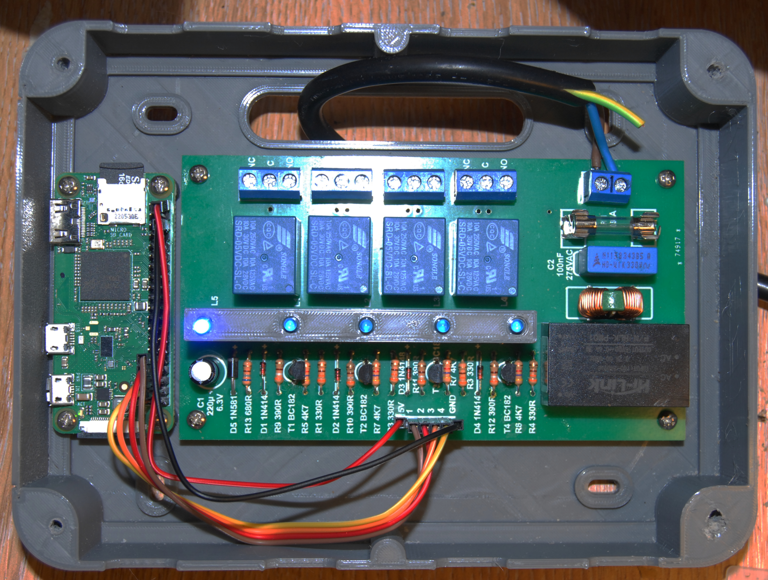
that can interface to a Pi if you want
Supply the voltage and have transistors and LEDS to drive and show relay status
http://vps.templar.co.uk/Odd%20stuff/HC.JPG
Its interfacing to a zero there, but a Pico can run off 5V as well
On 04/08/2025 11:10, The Natural Philosopher wrote:
On 04/08/2025 09:04, Mike Scott wrote:Thanks for the offer, but as I already have the 8-way bank, I'll settle
On 02/08/2025 12:44, Gordon Henderson wrote:I've got bare pcbs with a 5V psu and buffered 4 buffered relay coils
Personally, I think that if I already had a working bank of mechanical >>>> relays (with opto isolated inputs such as the multitude sold for
Adruino
and Pi) I'd just suck it up and give it a separate 5v PSU capable
Yes, sound advice. Thanks. I was working out late last night this
will be outside a normal usb current limit. I do have a suitable bank
of relays, and I'm pretty sure there must be a spare 5V wall wart
around somewhere.
Thanks to all for comments offered. I think I'll have to stick to the
old-fashioned way here.
that can interface to a Pi if you want
Supply the voltage and have transistors and LEDS to drive and show
relay status
http://vps.templar.co.uk/Odd%20stuff/HC.JPG
Its interfacing to a zero there, but a Pico can run off 5V as well
for that.
The relays are switching DC at 12V, but the polarity is determined
before the on/off relay. Most SS relays I've seen are triac-based for AC >only; one type would do DC, but not with the polarity changing (and at
10x the cost anyway!).
The relays are switching DC at 12V, but the polarity is determined
before the on/off relay. Most SS relays I've seen are triac-based for AC
only; one type would do DC, but not with the polarity changing (and at
10x the cost anyway!).
MOSFET based solid state relays
handle DC or AC and shut off immediately
whereas SCR or TRIAC turn off AC only at the zero crossing.
see:
https://www.ti.com/document-viewer/lit/html/SSZTB27
Can do. Most MOSFETS are unipolarThe relays are switching DC at 12V, but the polarity is determined
before the on/off relay. Most SS relays I've seen are triac-based for AC
only; one type would do DC, but not with the polarity changing (and at
10x the cost anyway!).
MOSFET based solid state relays
handle DC or AC and shut off immediately
whereas SCR or TRIAC turn off AC only at the zero crossing.
see:
https://www.ti.com/document-viewer/lit/html/SSZTB27
| Sysop: | DaiTengu |
|---|---|
| Location: | Appleton, WI |
| Users: | 1,089 |
| Nodes: | 10 (0 / 10) |
| Uptime: | 155:13:26 |
| Calls: | 13,921 |
| Calls today: | 2 |
| Files: | 187,021 |
| D/L today: |
3,924 files (993M bytes) |
| Messages: | 2,457,199 |